Lab 8 - Discrete Amplifier
Contents
1 Goals
In this lab, you will continue learning how transistors work by creating a dual-stage amplifier out of discrete transistors. The two stages of the amplifier can each be made from a single transistor; one stage will be a common emitter amplifier, and the other will be an emitter follower. We will use this as an audio amplifier.
Last week you learned some basics about bipolar junction transistors (BJT) and used LTspice to build some basic BJT circuits. This week we will get hands on experience with BJTs. You will also refine your ability to model and predict the behavior of BJTs.
1.1 Definitions
AC component of a voltage: \(v\) - A voltage \(V\) which has an AC signal riding on a DC offset can be defined as \(V=v+V_{DC}\), where \(v\) defines the amplitude of the AC signal and \(V_{DC}\) is the DC offset.
NPN - A BJT where positive current (current into the base) pulls current into the collector and out of the emitter.
PNP - A BJT where a negative current (current out of the base) pulls current into the emitter and out of the collector. It is simplest to think of a PNP as an NPN where all the currents are negative relative to an NPN.
Base current: \(I_B\) - The amount of current that flows into the base. This current controls the BJT.
Collector current: \(I_C\) - the current that is controlled by the base current.
Emitter current: \(I_E\) - The collector current and base current combine, such that \(I_E=I_C+I_B\).
Current gain: \(h_{FE}\) or \(\beta\) - The control current \(I_B\) is related to the controlled current \(I_C\) by the current gain, such that \(I_C = h_{FE}I_B\). This value generally depends on current and temperature.
Base voltage: \(V_B\) - the voltage at the base relative to ground.
Collector voltage: \(V_C\) - the voltage at the collector relative to ground.
Emitter voltage: \(V_E\) - the voltage at the emitter relative to ground.
Collector-emitter voltage: \(V_{CE}\) - The voltage difference between the collector and emitter.
Base-emitter voltage: \(V_{BE}\) - The voltage difference from the base to the emitter; when the transistor is active, this will be a diode-like voltage drop (about 0.6 V for silicon).
Coupling capacitor - A capacitor in series with a signal that essentially acts as a short for high frequencies and an open circuit for DC. This allows you to “couple” a signal into a circuit in a way that DC currents can’t flow back into the signal source.
Decoupling capacitor - A capacitor between a supply voltage and ground. This compensates for a power supply’s inductance and acts as a power reservoir. You have used these for powering your op-amp circuits.
1.2 Bipolar Junction Transistors - Review
You have seen how a BJT is a current amplifier. However because currents and voltages are related, it is possible to use current amplification to make a voltage amplifier. In this experiment we will build a simple two-stage voltage amplifier using two BJTs.
In many practical applications it is easier to use an op-amp as a source of gain rather than to build an amplifier from discrete transistors. A good understanding of transistor fundamentals is nevertheless essential because op-amps are built from transistors. We will learn later about digital circuits, which are also made from transistors. In addition to the importance of transistors as components of op-amps, digital circuits, and an enormous variety of other integrated circuits, single transistors (usually called “discrete” transistors) are used in many applications. They are important as interface devices between integrated circuits and sensors, indicators, and other devices used to communicate with the outside world. High-performance amplifiers operating from DC through microwave frequencies use discrete transistor “front-ends” to achieve the lowest possible noise. Discrete transistors can also be much faster than op-amps; for example, the device we will use this week has a gain-bandwidth product of 300 MHz (compared to 5 MHz for the LF356 op-amp you have been using).
As a refresher, the three terminals of a bipolar transistor are called the collector, base, and emitter (Figure 1). A small current into the base controls a large current flow from the collector to the emitter. This means that the transistor acts as a current amplifier with a current gain \(h_{FE}\) (or \(\beta\)). Moreover, the large collector current flow is almost independent of the voltage across the transistor from collector to emitter \(V_{CE}\). This makes it possible to obtain a large amplification of voltage by having the collector current flow through a resistor.

From the simplest point of view a bipolar transistor is a current amplifier. The current flowing from collector to emitter is equal to the base current multiplied by a factor. An NPN transistor like the 2N3904 operates with the collector voltage at least a few tenths of a volt above the emitter, and with a current flowing into the base. There are also PNP transistors with opposite polarity voltages and currents. The base-emitter junction acts like a forward-biased diode with a forward-voltage drop, where the forward voltage can be modeled as the threshold voltage \(V_{th}\):
\[V_E \approx V_B-V_{th}\]
\[V_{BE} \approx V_{th}\]
Where \(V_{th}\) is about \(0.6\text{ V}\) for silicon. Under these conditions, the collector current is proportional to the base current:
\[I_C = h_{FE}I_B\]
The constant of proportionality (‘current gain’) is called \(h_{FE}\) because it is one of the "h-parameters", which are a set of numbers that give a complete description of the small-signal properties of a transistor. It is important to keep in mind that \(h_{FE}\) is not a constant. It depends on collector current, and it can vary by 50% or more from device to device.
The emitter current can be determined by current conservation:
\[I_E = I_B+I_C = I_C\left(\frac{1}{h_{fe}}+1\right)\]
The difference between \(I_C\) and \(I_E\) is almost never important since \(h_{FE}\) is normally in the range between \(50\) and \(1000\), so you can generally assume that \(I_E = I_C\). Another way to say this is that the base current is very small compared to the collector and emitter currents.
2 Prelab
2.1 The 2N3904
The transistor you will use in this lab is the 2N3904, which is an NPN. The datasheet can be found in the Datasheets and Instrument Manuals page. Most NPNs have a “complement,” which is a PNP with very similar characteristics. The 2N3904’s complement is the 2N3906. We have 2N3906s in the lab, but we won’t need them in this lab; however, you may want them for your project.
The 2N3904 and 2N3906 have high current gain \((h_{FE})\), however, they are unable to deliver large amounts of current. This is fine, because the speakers we will use in this lab are very small and can only handle about half a Watt of power. If you want to power a larger speaker at higher power (louder), you will need transistors that can handle more current: often referred to as "power transistors." Power transistors often have much smaller current gain than other transistors, and sometimes they must be connected in pairs to increase the total gain (you can search for "Darlington connection" in Horowitz and Hill). We have a complementary pair of power transistors in the lab: 2N2222 (NPN) and 2N2907 (PNP). These may be useful for a project. It is typically easy to distinguish normal BJTs from power BJTs since power BJTs have ways of mounting heat-sink hardware to help dissipate the heat (a hole for a bolt to go through and a metallic surface for good thermal conductivity).
2.1.1 Prelab Question
- What is the maximum \(h_{FE}\) value at 10 mA collector current? See the 2N3904 data sheet posted in the Datasheets and Instrument Manuals page. For any calculation that requires \(h_{FE}\) throughout the prelab, you can use this value.
2.2 Emitter Follower
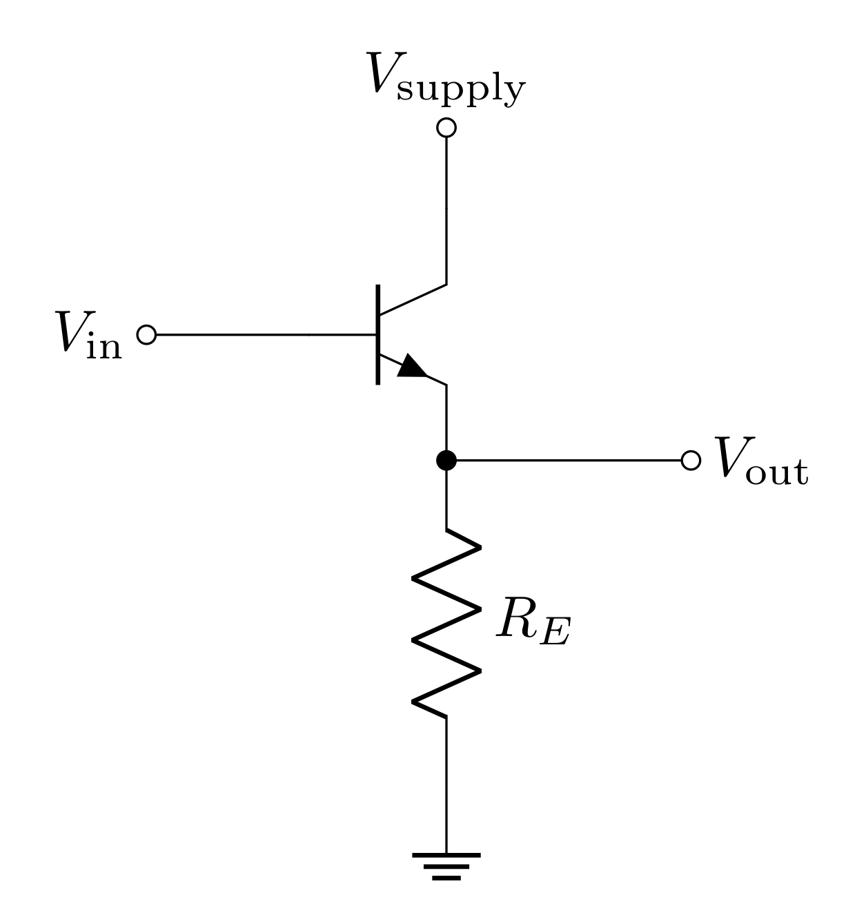
The emitter follower (EF) is a very simple BJT circuit that just involves a single BJT and a single resistor. This looks similar to the switch you designed last week. However, because the emitter is not directly grounded, it is not necessary to have a base limiting resistor (between \(V_\text{in}\) and the base); the emitter resistor \(R_E\) will limit the current.
The fact that this circuit is called a follower should clue you in to what its function is, which you will solve in the following questions.
We will analyze this circuit using the current amplifier model:
\(I_C = h_{FE} I_B\)
\(I_E = I_C + I_B = I_C (1 + 1/h_{FE})\)
The base-emitter junction acts like a diode.
2.2.1 Prelab Question
When \(V_\text{in}>V_{th}\), what will the base-emitter voltage \(V_{BE}\) be?
Use \(V_{BE}\) to determine \(V_\text{out}\) with respect to \(V_\text{in}\).
Describe the relationship between \(V_\text{in}\) and \(V_\text{out}\), and explain why this a follower.
2.2.2 Prelab Question
The emitter current can be determined by using Ohm’s law from the emitter to ground. In the circuit drawn, the impedance from the emitter to ground is just the emitter resistor \(R_E\). Use \(V_\text{out}\) to write an expression for \(I_E\).
Explain why we can assume \(I_E=I_C\)?
2.2.3 Prelab Question
The input impedance is defined by
\[R_\text{in} = \frac{V_\text{in}}{I_\text{in}}\]
where \(I_\text{in}\) is how much current the input draws at an applied voltage of \(V_\text{in}\). Since the input current \(I_\text{in}\) goes into the base, \(I_\text{in}=I_B\).
Write \(I_\text{in}\) with respect to \(I_C\) instead of \(I_B\).
Use Question 2.2.2.1 and 2.2.2.2 to create an expression for \(I_C\) to show
\[R_\text{in} = \frac{h_{FE}R_EV_\text{in}}{V_\text{in}-V_{th}}\]
Since \(V_{th}\) is typically small, this will often be approximated such that \(V_\text{in}-V_{th}\approx V_\text{in}\), so
\[R_\text{in} \approx h_{FE} R_E\]
Note: In this case, \(R_E\) represents the impedance of all the elements combined between the emitter and ground.
2.2.4 Prelab Question
As we’ve seen in other labs, output impedance \(R_\text{out}\) causes a voltage drop when output current flows so that not all of the predicted (or internal) voltage makes it to the load:
\[V_\text{out}^\text{(ext)} = \frac{R_L}{R_\text{out} + R_L}V_\text{out}^\text{(int)}\]
So output impedance can be represented as
\[R_\text{out} = R_L\bigg(\frac{V_\text{out}^\text{(int)}}{V_\text{out}^\text{(ext)}}-1\bigg)\]
where it can be determined experimentally by measuring \(V_\text{out}^\text{(int)}\) by measuring \(V_\text{out}\) with no load (no current draw) and \(V_\text{out}^\text{(ext)}\) with a load.
People will define output impedance as "the impedance looking into the output." For the emitter follower, this is
\[R_\text{out} = \frac{R_B}{h_{FE} +1}\]
where \(R_B\) indicates whatever impedance is connected to the base. To be more precise, one should also include the emitter resistor in parallel with \(R_\text{out}\) for the true output impedance of the circuit.
The circuit shown in Figure 2 does not have any impedance connected to the base, but if you use the function generator, the output impedance of the function generator will act as \(R_B\). What is \(R_\text{out}\) if you use the function generator for \(V_\text{in}\) and if the transistor has an \(h_{FE}=300\)?
If \(R_E = 800\ \Omega\), will this, appreciably change the output impedance?
2.3 Common Emitter Amplifier
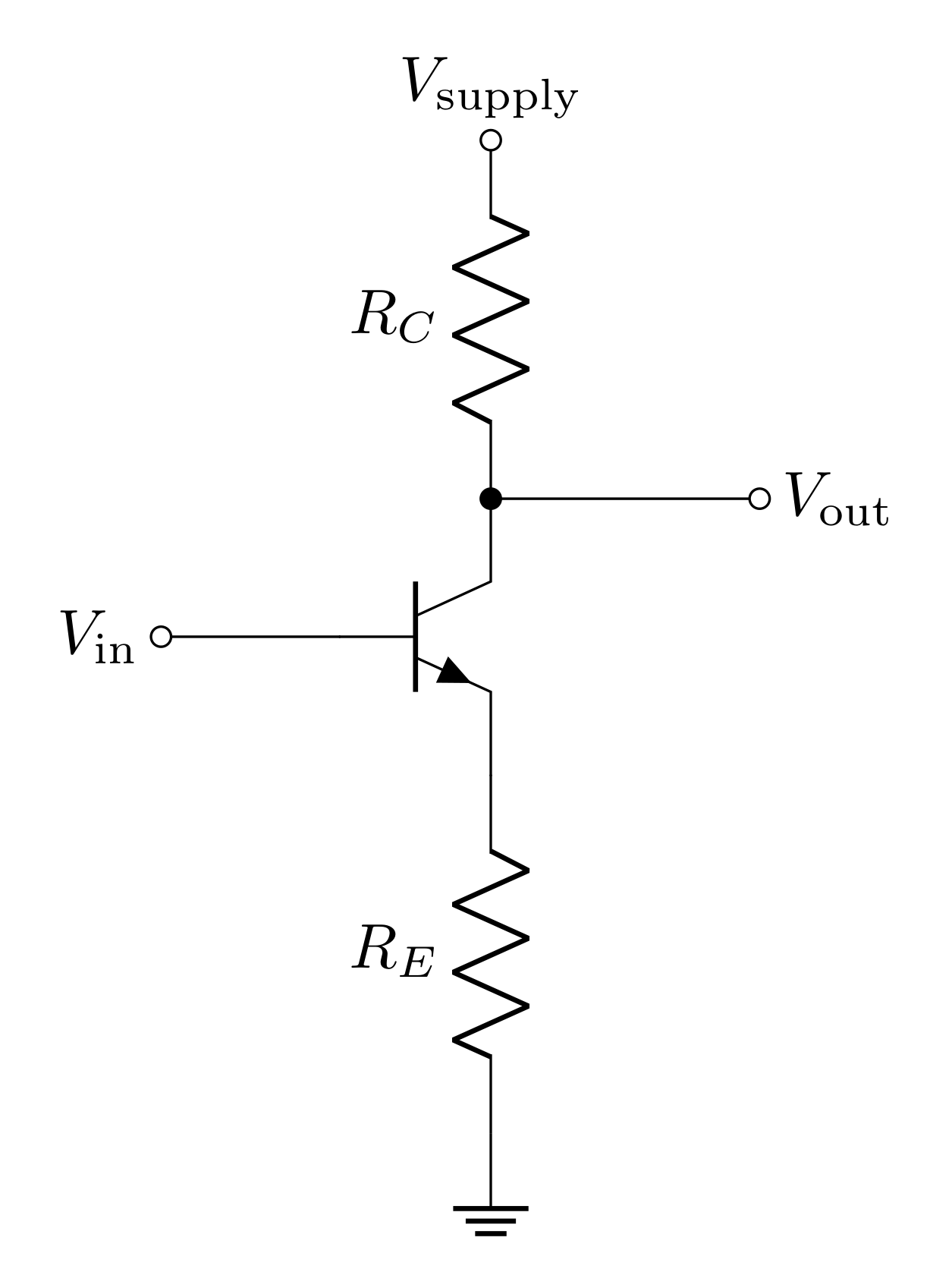
In the lab, you will begin by constructing a common emitter amplifier (CEA), which operates on the principle of a current amplifier. However, a major fault of the common emitter amplifier is its high output impedance. This problem can be fixed by adding an emitter follower as a second stage. The common-emitter amplifier and the emitter follower are two common bipolar transistor circuits.
The common emitter amplifier is similar to the emitter follower but with the output at the collector instead of the emitter and with a collector resistor \(R_C\). Again the base-emitter voltage \(V_{BE}\) will be \(V_{th}\) when active, so \(V_E = V_\text{in} - V_{th}\), and therefore
\[I_E = \frac{V_\text{in}-V_{th}}{R_E}\]
Since \(I_C\approx I_E\), we can then consider this as the current through \(R_C\), then the voltage drop across \(R_C\) can be used to determine \(V_\text{out}\)
\[V_\text{supply}-V_\text{out} = I_C R_C \approx I_E R_C\]
\[V_\text{out} = V_\text{supply} - \frac{R_C}{R_E}(V_\text{in}-V_{th}) \]
This analysis suggests that the output rides on a DC offset of \((V_\text{supply}+V_{th} R_C/R_E)\). Trying to define the gain as \(V_\text{out}/V_\text{in}\) clearly leads to a weird result. It is better to define it in terms of only the AC component of the signal.
\[G = \frac{v_\text{out}}{v_\text{in}}\]
where
\[v_\text{out} = -v_\text{in}\frac{R_C}{R_E}\]
so
\[G = -\frac{R_C}{R_E}\]
Notice how none of this depended on the specific value of \(h_{FE}\). This is a good thing because \(h_{FE}\) is not a constant, so the amplifier can act stable under various conditions.
2.3.1 Prelab Question
When \(V_\text{in}<V_{th}\), is the transistor active?
When \(V_\text{in}<V_{th}\), what is \(I_C\)?
When \(V_\text{in}<V_{th}\), what is \(V_\text{out}\)?
2.3.2 Prelab Question
Consider the common emitter amplifier with
\(V_\text{supply}=15\text{ V}\),
\(R_C=2.74\text{ k}\Omega\),
\(R_E=1\text{ k}\Omega\).
- What is the voltage gain?
Consider an input signal that is a sine wave that oscillates around \(0\text{ V}\) with an amplitude of \(4\text{ V}\) (\(8\text{ V}\) peak-to-peak)
- Sketch a plot (you can use Python) with \(V_\text{in}\) and \(V_\text{out}\). Hint: consider your solutions in Question 2.3.1.
2.3.3 Prelab Question
We found that the output will clip at a maximum of \(V_\text{max} = V_\text{supply}\) when \(V_\text{in}<V_{th}\). Now consider the clipping for the minimum value of \(V_\text{out}\); i.e. \(V_\text{min}\). The equation for the output voltage can be rewritten
\[V_C = V_\text{supply}-\frac{R_C}{R_E}(V_B-V_{th}) = V_\text{supply}-\frac{R_C}{R_E}V_E\]
by recognizing that \(V_\text{out}\) is the collector voltage \(V_C\) and \(V_\text{in}\) is the base voltage \(V_B\). We can determine the lower clipping value by knowing that it is impossible for \(V_{CE}\) to be negative. This can also be stated that \(V_C\) must be greater than \(V_E\):
\[V_C\ge V_E\]
You can determine the minimum \(V_C\) \((V_\text{out})\) by finding the value of \(V_C\) that occurs when \(V_C=V_E\). Use this condition to express the minimum \(V_C\) with respect to \(V_\text{supply}\), \(R_C\), and \(R_E\).
Determine the minimum output voltage for \(V_\text{supply}=15\text{ V}\), \(R_C=2.74\text{ k}\Omega\), and \(R_E=1\text{ k}\Omega\).
What is the maximum input voltage that corresponds to this minimum output voltage (recall this is an inverting amplifier)? Hint: Express the equation above under the \(V_C=V_E\) condition in terms of \(V_E\) instead of \(V_C\) and then express it in terms of \(V_B\). Recall: \(V_E=V_B-V_{th}\).
2.3.4 Prelab Question
The input impedance of the common emitter amplifier is the same as the emitter follower, since we can follow the same logic and steps to arrive at the solution. The output impedance, however, is different because the output is connected to the collector instead of the emitter. "Looking back at" the collector from the output sees two paths, one through the collector resistor \(R_C\), and one through the collector itself (which is a very large impedance). These two impedances can be thought of as in parallel.
- If \(R_C\ll\text{(the impedance looking into the collector)}\), what is \(R_\text{out}\)?
2.4 Quiescent Voltage and Biasing a Transistor Amplifier
Your plot in Question 2.3.2 shows that the common emitter amplifier is unable to effectively amplify signals that oscillate around \(0\text{ V}\) due to the fact that the output signal gets clipped at \(V_\text{supply}\). One solution to this issue is to ‘bias’ the input of the amplifier so that the input oscillates around a DC offset instead of around \(0\text{ V}\). You found above that when the input voltage is less than the threshold voltage, \(V_\text{out}=V_\text{supply}\). We can define the quiescent voltage as:
DEFINITION: Quiescent voltage: \(V_Q\) - the DC voltage at an output terminal with reference to ground when no signal is applied. Note: quiescent means ‘at rest’.
So the common emitter amplifier we considered above has a quiescent voltage \(V_Q=V_\text{supply}\). This clearly is a major issue since the maximum clipping voltage is also \(V_\text{supply}\). In order to amplify signals that oscillate around zero, the quiescent voltage needs to be lowered (to roughly halfway between the clipping voltages). Consider the circuit below:
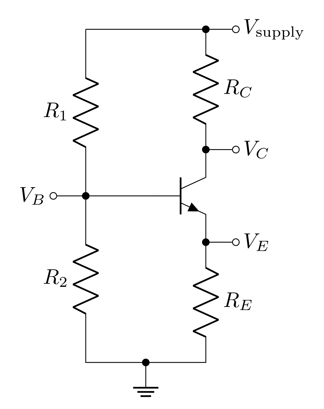
\(R_1\) and \(R_2\) form a voltage divider to set a ‘static state’ voltage at the base of the BJT. The transfer function of the bias network is
\[T_\text{bias} = \frac{R_2}{R_1+R_2}\]
This makes the ‘static state’ base voltage
\[V_B = \frac{R_2}{R_1+R_2}V_\text{supply}\]
The base voltage should be above the threshold voltage such that the transistor is active in the ‘static state,’ so
\[V_E = \frac{R_2}{R_1+R_2}V_\text{supply} - V_{th}\]
The ‘static state’ current through \(R_E\) is then
\[I_E = \frac{V_E}{R_E} = \frac{1}{R_E}\bigg(\frac{R_2}{R_1+R_2}V_\text{supply} - V_{th}\bigg)\]
Assuming \(I_C=I_E\), the collector voltage, and therefore the quiescent voltage, can be determined
\[V_Q = V_C = V_\text{supply} - I_CR_C = \bigg(1-\frac{R_CR_2}{R_E(R_1+R_2)}\bigg)V_\text{supply} + \frac{R_C}{R_E}V_{th}\]
2.4.1 Prelab Question
The circuit you will build will use a supply voltage of \(V_\text{supply}=15\text{ V}\) and collector and emitter resistors of \(R_C=2.74\text{ k}\Omega\) and \(R_E = 1\text{ k}\Omega\) (you already determined the AC voltage gain for these resistance values). We need to set a quiescent voltage that is roughly half way between the two clipping voltages.
What quiescent voltage is halfway between the two clipping voltages?
Determine the ‘static state’ base voltage value that will result in the quiescent voltage you determined.
If \(R_2=10\text{ k}\Omega\), what value of \(R_1\) will result in the desired quiescent voltage? Hint: This voltage will be the output of the bias network (voltage divider), so you will be looking to solve for \(V_\text{supply}R_2/(R_1+R_2)\).
What is the ‘static state’ collector current \(I_C\)?
2.4.2 Prelab Question
In the next section, we will detail how to connect the input to this circuit. However, it is important to consider the effects the biasing network will have on the input impedance. The input voltage will now have two new paths, leading to three total paths: (1) through \(R_1\), (2) through \(R_2\), and (3) into the base.
- We can treat all three of these as parallel impedances. You worked out the impedance into the base already (input impedance for the common emitter amplifier). Write an expression for the input impedance of the common emitter amplifier with a biasing network.
The biasing network won’t impact the output impedance because it will still be dominated by \(R_C\) (the impedance looking into the collector will still by very large).
2.5 Completing the Common Emitter Amplifier
A simple way to add a DC voltage and an AC voltage is to simply connect them together; however, this can lead to currents flowing into the source of the AC voltage (the function generator), which can lead to issues (like breaking the function generator). To mitigate this, a coupling capacitor should be used to couple the AC signal into the circuit. Since a capacitor acts as an open circuit to DC currents, the bias network will be unable to send a current back into the function generator.
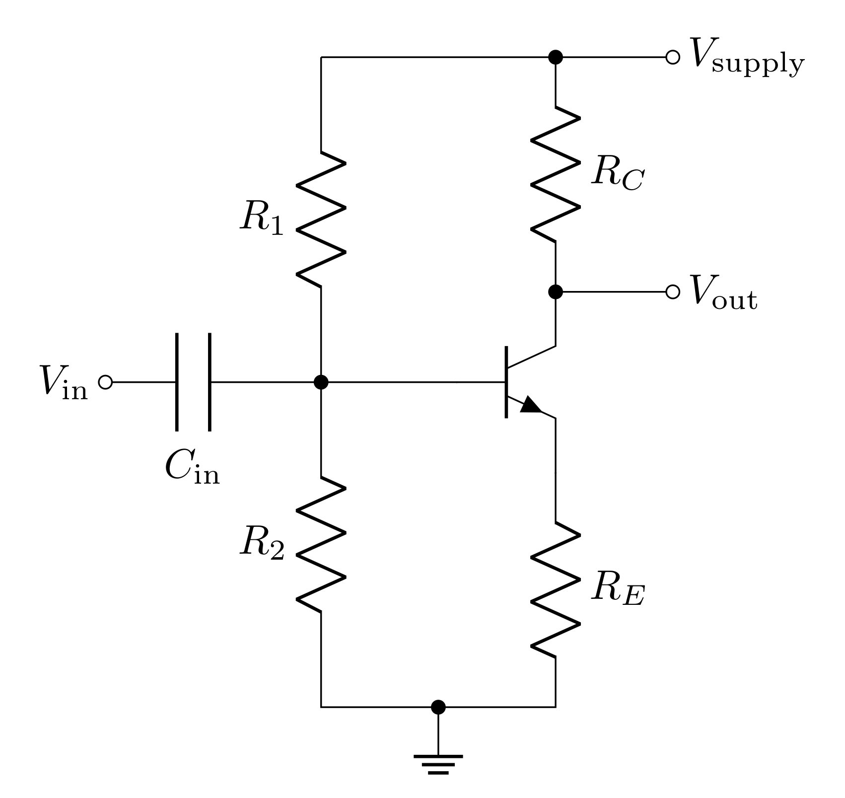
The signal at the base then will be the addition of the DC bias set by the biasing network and the AC signal set by \(V_\text{in}\). If \(v_\text{in}\) is the AC component of \(V_\text{in}\), then
\[V_B = v_\text{in} + \frac{R_2}{R_1+R_2}V_\text{supply}\]
Note: If \(V_\text{in}\) is purely an AC signal, then \(v_\text{in}=V_\text{in}\). Otherwise, \(v_\text{in}=V_\text{in}-V_{DC}\), where \(V_{DC}\) is the DC part of \(V_\text{in}\).
Another issue we haven’t considered, yet, is the fact that the power supply has series inductance. Therefore, the current through \(R_C\) (which is responsible for setting \(V_\text{out}\)) cannot change without disrupting the voltage supplied to the circuit (we discussed this in detail for lab 4). The solution is to add a decoupling capacitor between the supply voltage and ground.
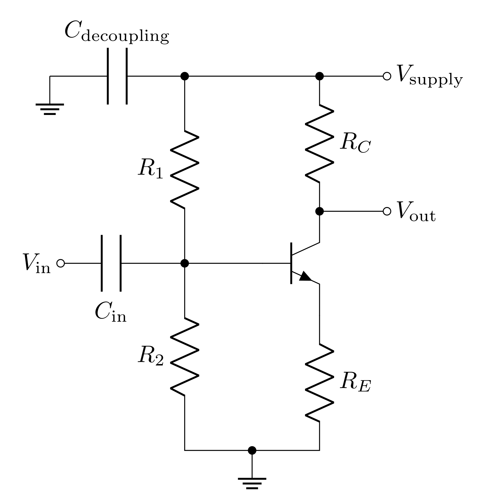
Finally, the output of the circuit will oscillate around the quiescent voltage. We can show this by solving the circuit:
\[V_E = V_B - V_{th} = v_\text{in} + \frac{R_2}{R_1+R_2}V_\text{supply} - V_{th}\]
So
\[I_C=I_E = \frac{v_\text{in}}{R_E} + \frac{R_2}{R_E(R_1+R_2)}V_\text{supply} - \frac{V_{th}}{R_E}\]
And finally
\[V_\text{out} = \bigg(1-\frac{R_CR_2}{R_E(R_1+R_2)}\bigg)V_\text{supply} + \frac{R_C}{R_E}V_{th} - \frac{R_C}{R_E}v_\text{in} = V_Q - \frac{R_C}{R_E}v_\text{in}\]
\(V_Q\), as we discussed previously, is just the DC offset at the output, so the AC component of \(V_\text{out}\) is
\[v_\text{out} = -\frac{R_C}{R_E}v_\text{in}\]
To access just the AC component, you can simply use the AC coupling feature on the oscilloscope to remove the quiescent voltage from the measurement. However, in order to only send the AC component to a load, you will need to use a coupling capacitor to send the AC signal across while blocking the quiescent voltage.
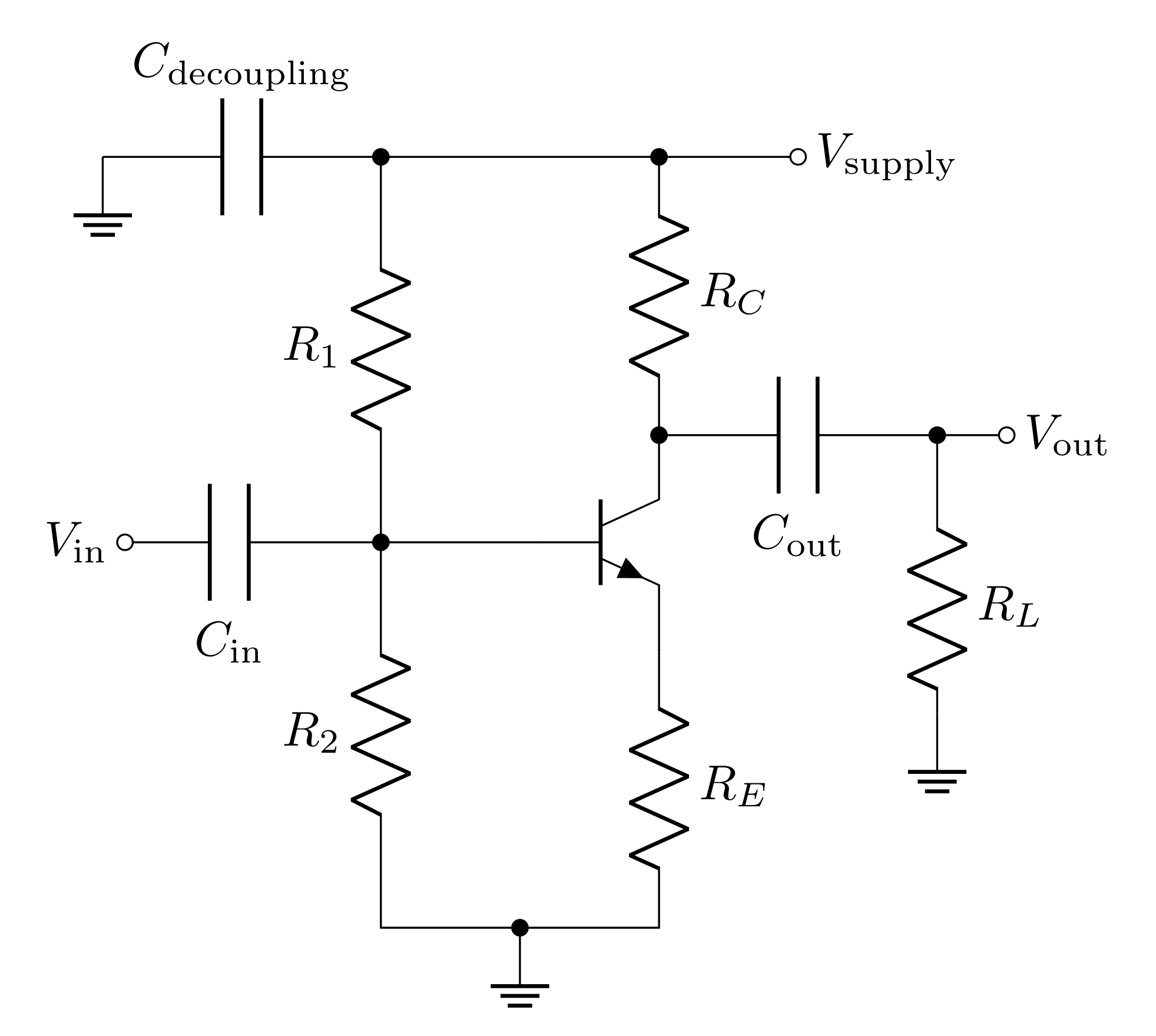
This circuit above is a "complete" common emitter amplifier. The resistors \(R_C\) and \(R_E\) set the AC voltage gain. The resistors \(R_1\) and \(R_2\) bias the transistor and set the quiescent voltage \(V_Q\). The input coupling capacitor \(C_\text{in}\) allows you to safely add \(v_\text{in}\) (the AC component of \(V_\text{in}\)) to the voltage set by the biasing network formed by \(R_1\) and \(R_2\). The decoupling capacitor provides a power reservoir and offsets the effects of the power supply’s series inductance. And finally the output coupling capacitor \(C_\text{out}\) blocks the DC offset (quiescent voltage) while passing the AC signal to the load \(R_L\).
2.5.1 Prelab Question
Notice that the output coupling capacitor and the load form a RC filter (like the ones we studied in lab 3).
Is this a low pass or a high pass filter?
Write an expression for the cutoff frequency of the filter.
Explain, from the perspective of the filter, how the coupling capacitor "blocks" the quiescent voltage from getting to the load.
2.5.2 Prelab Question
Draw the diagram in Figure 7 in your lab notebook with the values used in the prelab. For example \(V_\text{supply}=15\text{ V}\), \(R_C=2.74\text{ k}\Omega\), \(R_E=1\text{ k}\Omega\), and \(R_2=10\text{ k}\Omega\). You found \(R_1\) in Question 2.4.1. For the capacitors, the exact value isn’t critical for the function of the amplifier, but \(47\ \mu\text{F}\) is a good value for the decoupling capacitor and \(C_\text{out}\), and \(220\text{ nF}\) is a good value for \(C_\text{in}\). The load does not need a label because we will consider different loads in the lab.
These will be the values you will use in the lab and to solve the remaining problems in the prelab.
2.6 Ebers-Moll Model of a Bipolar Transistor
We have been considering the current-amplifier model, where we use \(I_C=h_{FE}I_B\) and treat the base-emitter junction like a diode to predict the behavior of the circuit. This is a good model, but for some applications, treating the transistor as a transconductance device is more informative and accurate. This is called the Ebers-Moll model, and in this model, the collector current \(I_C\) is determined by the base-emitter voltage \(V_{BE}\) (which in reality is nearly \(V_{th}\), but increases slightly as a function of \(I_B\)):
\[I_C = I_S\bigg(e^{V_{BE}/V_T}-1\bigg)\]
where \(I_S\) is the saturation current of the particular transistor (which is temperature dependant), \(V_T = k_BT/e=25.2\text{ mV}\) at room temperature \((\sim300\text{ K})\), \(k_B\) is Boltzmann’s constant, and \(e\) is the electron’s charge.
For our purposes, the Ebers-Moll model modifies our current-amplifier model of the transistor in only one important way. For small variations about the quiescent point, the transistor now acts as if it has a small internal resistor, \(r_e\), in series with the emitter. The magnitude of the intrinsic emitter resistance, \(r_e\), depends on the collector current \(I_C\):
\[r_e = 25\ \Omega \left(\frac{1\text{ mA}}{I_C}\right)\]
The presence of the intrinsic emitter resistance, \(r_e\), modifies the above input impedances to:
\[R_\text{in} = (R_e + r_e)\ h_{FE}\]
where \(R_e\) is the total impedance of the resistors connected between the emitter and ground. If this is only the resistor, \(R_E\), then \(R_e=R_E\). This is true for both the emitter follower and the common emitter amplifier. Note: With the biasing network, \(R_1\) and \(R_2\) will be in parallel with this for the true input impedance
The output impedance of the emitter follower can then be shown to be
\[R_\text{out} = \frac{R_B}{h_{FE}+1}+r_e\ \ \text{(EF)}\]
The common emitter amplifier’s output impedance doesn’t change because it does not depend on the resistance past the emitter. However, it does modify the gain of the common emitter amplifier to:
\[G = \frac{-R_C}{R_e+r_e}\]
which shows that the common emitter gain is not infinite when the external emitter resistor goes to zero.
For the following questions, use the component values in the circuit diagram you made.
2.6.1 Prelab Question
Calculate the input impedance \(R_\text{in}\) of the circuit you designed. Don’t forget to consider the fact that the biasing resistors are in parallel with common emitter amplifier’s intrinsic input impedance. Hint: Use the static state \(I_C\) you determined above to find \(r_e\).
What is the output impedance of the common emitter follower you drew a diagram for?
Calculate the fraction of the original amplitude obtained when a \(470\ \Omega\) load is attached. HINT: the \(470\ \Omega\) resistor is in series with the output impedance of the circuit to ground. The output capacitor only blocks the DC component; it passes the AC signal just fine.
2.6.2 Prelab Question
A standard non-amplified speaker has an input impedance of \(8\ \Omega\). If your computer headphone jack had an output voltage at \(1\text{ V}\) unloaded and an output impedance of \(8\ \Omega\), what would the loaded voltage be if you hooked it up to the \(8\ \Omega\) speaker?
Now, instead you can use the common emitter to amplify the signal from the computer first. For the same \(1\text{ V}\) AC signal, what will the output voltage be. Consider both the AC voltage gain and the output impedance.
2.7 Dual Stage amplifier
As you found above, the output impedance of the amplifier you designed is quite high and makes it impractical for driving small loads. Load impedances are often small; for example, speakers are typically \(4\ \Omega\), \(6\ \Omega\), or \(8\ \Omega\). This makes \(R_L/(R_\text{out}+R_L)\approx0\). The emitter follower has a large input impedance, so it will not draw much current from amplifier, and therefore, barely any voltage will drop across the output impedance. The emitter follower, having a very small output impedance, will then be able to deliver the voltage to the load in a more practical way.
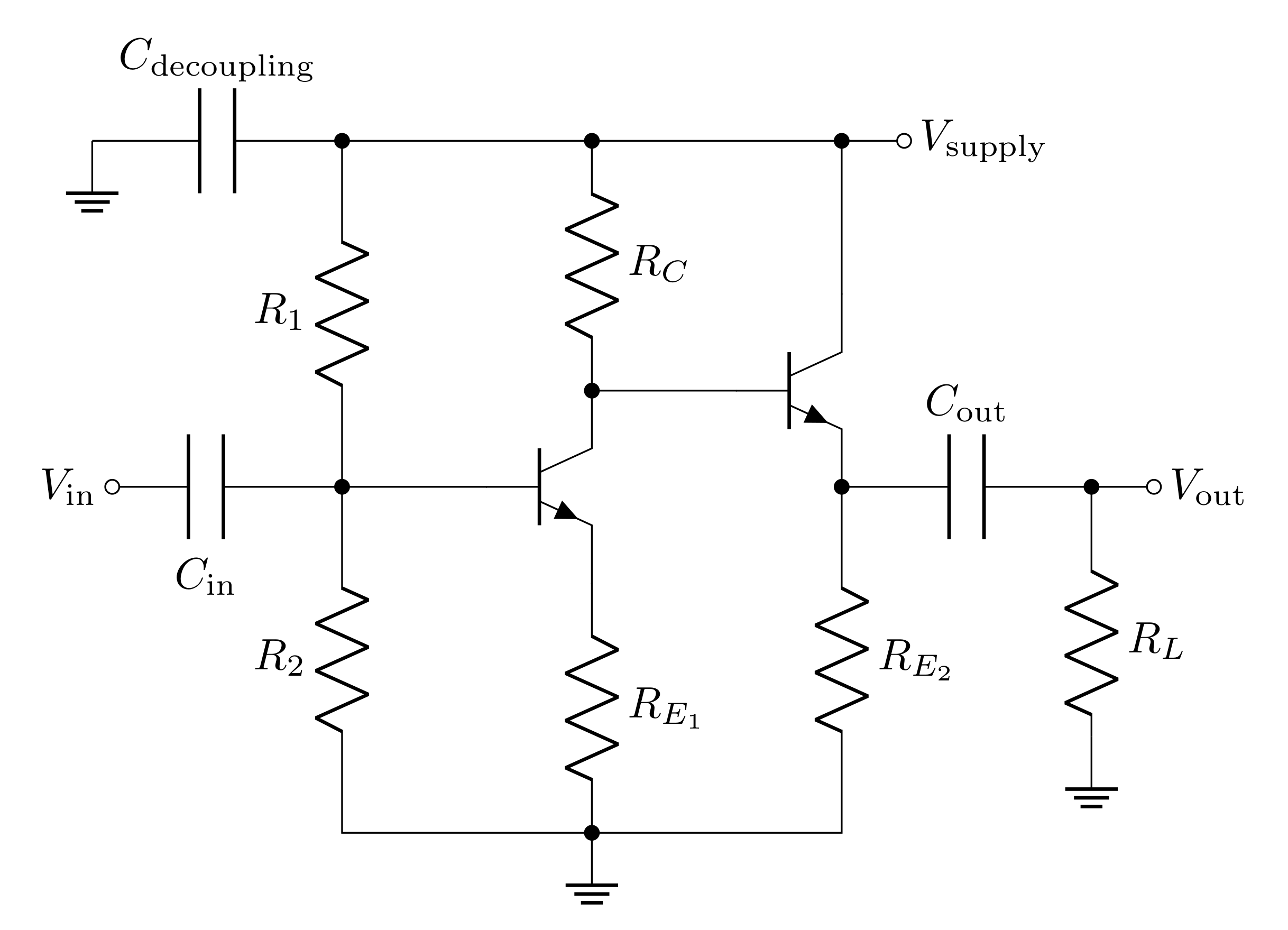
2.7.1 Prelab Question
Draw the dual stage amplifier in your lab notebook and label all the components. The first stage will have all the same values as the amplifier you designed above. Use \(820\ \Omega\) for the emitter resistor of the second stage.
2.7.2 Prelab Question
What is the input impedance of the second stage when no load is attached, and what is it when a load of \(8\ \Omega\) is attached?
The output impedance of the second stage depends on the impedance connected to the base. In this case, the output impedance of the first stage will be the impedance leading into the base. Calculate the output impedance of the whole circuit.
Calculate the fraction of the output will make it to an \(8\ \Omega\) load.
What is the output voltage when the input is \(1\text{ V}\) amplitude? Consider both the voltage gain and the transfer function you calculated above.
2.8 Lab activities
2.8.1 Prelab Question
Please review the lab activities so that you’re better prepared when you arrive to your lab section.
3 Useful Readings
You can find more on BJTs in these recommended sources:
Steck Sections 4.1, 4.2, 4.3, 4.4, 4.6, 4.6.1, 4.8, 4.9, and 4.11.3
Fischer-Cripps Chapters 5 and 6
Horowitz and Hill Chapter 2 (in both editions). There are sections on both the emitter follower and the common emitter amplifier, and a section on the Ebers-Moll model. It’s a long chapter, but it is worth thumbing through for your final project.
4 Lab activities
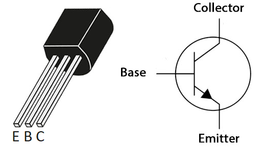
4.1 Common Emitter Amplifier
4.1.1 Quiescent scale
First you will build the common emitter amplifier with the biasing network, but without an input voltage, to be able to measure the ‘static state’ of the amplifier.
Build the version of the common emitter amplifier shown in Figure 5 without the capacitors \(C_\text{in}\) and \(C_\text{out}\) (and without \(V_\text{in}\)). Measure the resistors before putting them in the circuit, and if they differ from the values used in your calculations, recalculate the predicted quiescent voltages. Draw the circuit schematic in your lab book and label all components.
Measure the DC voltages (quiescent voltages) \(V_B\) (at the transistor base), \(V_E\) (at the emitter), and \(V_C\) (at the collector)? Do they agree with your predictions from your prelab?
4.1.2 Check limits with AC signal
Before you apply the input signal, consider the fact that the signal will cause the current draw from the power supply to fluctuate. This means we’ll need to use a capacitor to decouple the power supply. Use a \(47\ \mu\text{F}\) as a decoupling capacitor. You will need to place this capacitor with the correct orientation to avoid destroying it.
DO NOT CONNECT THE FUNCTION GENERATOR DIRECTLY TO THE BASE OF THE BJT! Add the input coupling capacitor \(C_\text{in}\) and the input AC source \(V_\text{in}\) (and use the sync output to trigger the scope). The capacitor allows one to transmit an AC signal while maintaining the DC voltages established by the bias network. When you switch on the power, you may see high frequency spontaneous oscillations. These must be suppressed before you can proceed. Also, reducing the length of your circuit wires can help. Do not add \(C_\text{out}\) yet.
Assemble a test setup to observe the input (before \(C_\text{in}\)) and output of the amplifier with \(10\text{ kHz}\) sine waves. Check that your setup works, and you can measure both the input and output.
For the scope channel connected to the output, switch the coupling between DC and AC coupling and adjust the scope to see the signal in both cases. Explain the different behavior and say why you may want one or the other.
Which coupling mode should you use to determine the AC gain? Use that mode to determine the AC gain and compare it to your prediction.
In order to determine the clipping, we want to know the absolute voltage that clipping occurs, this means we DO NOT WANT AC COUPLING on to determine this. Vary the input amplitude to determine the output amplitude at which clipping begins. Compare the clipping voltage to the prediction in the prelab. Describe why the \(V_\text{min}\) clipping is not flat. Check in with an instructor about the clipping behavior.
4.1.3 Measuring the AC gain
Add the output coupling capacitor \(C_\text{out}\) as you designed in the prelab. It will be polarized. Since the left side is connected to a positive DC voltage of \(V_C\) and the right side will be connected to ground through the scope, you should have the negative side (the one that is marked and has the shorter lead) on the right. Move your scope measurement to occur after \(C_\text{out}\). When you first turn it on, you may find that the output voltage has a large DC offset due to charging of the output coupling capacitor. This should discharge since the scope provides a \(1\text{ M}\Omega\) path to ground but if it doesn’t, you can add a \(220\text{ k}\Omega\) resistor to ground after \(C_\text{out}\). Check that the output now oscillates around \(0\text{ V}\) with the scope channel set to DC coupling.
Measure the gain of the amplifier for \(10\text{ kHz}\) sine waves using an amplitude that ensures the voltages are less than half of the clipping voltage (either positive or negative). You should use the 10x scope probe for measuring the output. Does your measurement agree with your prediction? Screen shots here would be good.
4.1.4 Output impedance
The common emitter amplifier often has a large output impedance. Connect a \(470\ \Omega\) load from the output to ground. What fraction of the original output do you now see? Does this agree with your prediction from section? If not, can you use your measurements of the output voltage before and after the resistor was in place to refine the model of your amplifier’s output impedance?
Remove the \(470\ \Omega\) load resistor.
Measure the impedance of your speaker with the DMM.
Attach the speaker to your circuit board. Connect the black wire to ground and connect the red wire to a free row on the circuit board. Drive the speaker directly with the function generator output. You should hear a tone. Vary the frequency and amplitude to check the effect on the output of the speaker. Then setup the same amplitude that you used in the previous section and a frequency of \(1\text{ kHz}\).
Switch back to driving the common emitter amplifier circuit with the function generator and connect the speaker to the output, just like you did with the \(470\ \Omega\) load resistor. Describe the results of both speaker tests. Does the gain provided by the common emitter amplifier result in a louder tone from the speaker? Explain your results.
4.2 Dual Stage Amplifier
4.2.1 Quiescent scale
Ordinarily, the quiescent voltage, is determined by a bias circuit (as was done for the common emitter stage). In the present case, the collector voltage \(V_C\) of the previous circuit already has a DC offset (the quiescent voltage of the first stage) suitable for biasing the emitter follower, so a direct DC connection can be made between the two circuits. Add the emitter follower to your circuit to build the dual stage amplifier as you drew in your lab notebook for the prelab.
Using your measured resistor values, calculate the DC voltages for the emitter follower’s base, emitter, and collector.
Measure the quiescent (DC) voltages (\(V_B\), \(V_E\), \(V_C\)) for the emitter follower part (you should disconnect the function generator from the circuit). Do the measurements agree with your predictions? Correct for/reconcile any errors before proceeding.
4.2.2 Low frequency AC gain
- Drive the complete system with the function generator at \(10\text{ kHz}\). Measure the AC amplitudes at the input of the common emitter, the input of the emitter follower, and at the output. What is the gain of the full circuit? What is the gain of just the emitter follower? Do these measurements agree with your predictions? HINT: As before, you may need a \(220\text{ k}\Omega\) resistor to ground after \(C_\text{out}\) to keep the DC level near ground as the large output capacitor can slowly charge up. You may also want to put the scope on AC coupling when you probe points with large DC offsets but switch it back to DC coupling if you want to measure quiescent voltages.
4.2.3 Output impedance
The emitter follower amplifier should have a low output impedance. Connect a \(470\ \Omega\) load from the output to ground. What fraction of the original output do you now see? Does this agree with your prelab predictions? If not, can you use your measurements of the output voltage before and after the resistor was in place to refine the model of your amplifier’s output impedance?
Remove the load resistor and drive a speaker with the output of the amplifier. Explain how you hooked up the speaker. Drive your amplifier with the function generator. Describe your measurements and observations. Do they agree with your model of the output impedance of the dual stage amplifier? Compare your results with the output from just the common emitter amplifier. Do the results make sense?
Next you will use your computer (or phone) to drive the speaker. Before doing this, remove the function generator from the circuit.
Now drive your amplifier with the audio source (computer). Describe your measurements and observations. Do they agree with your model of the output impedance of the dual stage amplifier?