Lab 4 - Operational Amplifiers (OP-Amps) I
Contents
1 Goals
In this lab you will get your first exposure with op-amps and use them to build two incredibly useful circuits: the voltage buffer (aka voltage follower), and the non-inverting amplifier. These two circuits are closely related and are used in many applications.
Op-amps serve many purposes, but one of the main uses is to amplify a small signal by increasing the voltage level while preserving as accurately as possible the original waveform. In real physics experiments, transducers are used to convert basic physical quantities into electric signals, as shown in Figure 1. An amplifier is usually needed to raise the small transducer voltage (μV to mV) to a useful level (mV to V) for the signal to be measured reliably.

Even though there are commercial amplifiers available for purchase, they are often very expensive (>$1000) and have many features that may not be needed. Meanwhile, you can design your own simple amplifier with an op-amp which could cost less than a dollar.
To prepare for this lab, you will learn to apply new analysis techniques (the op-amp golden rules) to predict the behavior and inform the design of op-amp circuits. In this lab, you will:
Explore obstacles due to the function generator’s output impedance.
Learn how to easily test an op-amp to see if it’s working.
Build a voltage buffer (follower) to
- provide a voltage with low output impedance,
- test the maximum output current of the LF356 op-amp.
Build a non-inverting amplifier to amplify small signals and test
- the gain,
- the frequency dependence,
- the maximum output voltages,
- the effects of resistors in series with the input,
- the output impedance and its effects on driving a load.
2 Prelab
2.1 Op-amps
The op-amp is, essentially, a “perfect part”: a complete integrated amplifier gain block, best thought of as a dc-coupled differential amplifier with single-ended output, and with extraordinarily high gain. It also excels in precise input symmetry and nearly zero input current. Op-amps are designed as “gain engines” for negative feedback, with such high gain that the circuit performance is set almost entirely by the feedback circuitry. Op-amps are small and inexpensive, and they should be the starting point for nearly every analog circuit you design. In most op-amp circuit designs we’re in the regime where they are essentially perfect: with them we will learn to build nearly perfect amplifiers, current sources, integrators, filters, regulators, current-to voltage converters, and a host of other modules. (Horowitz and Hill 3rd Ed. 223)
In this lab, you will use op-amps to build a voltage buffer and a non-inverting amplifier. Op-amps are ICs (integrated circuits) made up of many transistors. Most textbooks discuss transistors prior to op-amps; we are going in the opposite order because we are not particularly interested in how op-amps are designed and the details of the inner workings (however, this could be explored in a final project). When considering how op-amps work at a higher level, the analysis is often far easier than that of transistor circuits. The GOLDEN RULES can be used to solve most op-amp circuits with relative ease; these golden rules are approximations (which most of the time are quite accurate) that greatly reduce the complexity of op-amp circuit analysis.
2.2 Open Loop Gain
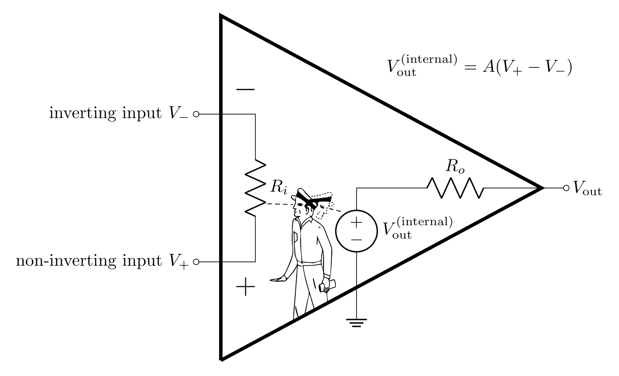
The op-amp has two inputs (inverting and non-inverting) and one output. It can be thought of as a “black-box” (as seen in Figure 2) which has an internal voltage source that is controlled by the potential difference between the non-inverting input and the inverting input. The op-amp’s output is the difference between the inputs times the open-loop gain \(A\).
\[V_\text{out} = A (V_+-V_-)\]
Note that this is true when there is no voltage drop across \(R_o\). Op-amps have very small output impedance, and for an ideal op-amp, \(R_o=0\).
Definition 1: Open-loop gain, \(A\) - the gain of the op-amp when there is no feedback.
The open-loop gain depends on frequency according to the following equation:
\[A(f) = \frac{A_\text{VOL}}{1+j\frac{f}{f_0}}\]
where \(A_\text{VOL}\) is the open-loop DC gain and \(f_0\) is the open-loop 3 dB point. Notice that this is the same kind of equation as a low-pass filter. At low frequencies, this equation is flat and equal to \(A_\text{VOL}\), but near the 3 dB point, it starts to drop (this drop is typically described in dB/octave or dB/decade) and can be reported in strange units like V/mV (which is essentially a weird way of writing \(10^3\)).
Definition 2: Open-loop DC gain, \(A_\text{VOL}\) - The open-loop gain at low frequencies before the frequency dependence starts to take over and the open-loop gain starts to decrease. This is cited in any op-amp datasheet (sometimes as \(A_\text{OL}\) or \(A_\text{VO}\)).
Definition 3: Open-loop 3 dB point, \(f_0\) - The frequency that the open-loop gain falls -3 dB from \(A_\text{VOL}\). Beyond this frequency, \(A\) typically continues to fall with a constant dB per log-scale (quoted in dB/octave (log2) or dB/decade (log10)). This value is usually not quoted in datasheets. It can be calculated from other values, and people often aren’t concerned with the value of \(f_0\).
An ideal op-amp has an open-loop gain of infinity and does not depend on frequency. Treating the gain as infinite is usually a really good approximation because real op-amps have open-loop gain values of \(10^5-10^8\). This approximation is known as the first GOLDEN RULE of op-amps.
GOLDEN RULE 1: The open-loop gain is infinitely large: \(A\rightarrow\infty\).
2.2.1 Prelab Question
In this lab, you will be using the LF356 op-amp. Open up its datasheet on the Datasheets and Instrument Manuals page. You should keep this open, as you’ll refer to it multiple times throughout the prelab and lab activities. Starting on page 2 there are tables with values for various properties of this op-amp and other closely related op-amps (make sure you pull values from the right column).
What is the open-loop DC gain, \(A_\text{VOL}\)? Report it as a unitless number.
2.3 Input impedance
Op-amps have input terminals that are designed to have very large input impedances (\(R_i\) in Figure 2), such that virtually no current can flow into or out of the inputs. The second GOLDEN RULE assumes that the input impedance is infinitely large and no current flows in or out of the inputs.
GOLDEN RULE 2: No current flows in or out of the inputs: \(I_+=I_-=0\).
2.3.1 Prelab Question
According to the datasheet, what is the input impedance (resistance) \(R_i\)?
2.4 Output current
Op-amps have very low output impedances (\(R_o\) in Figure 2) allowing them to efficiently drive loads (think back to the input and output impedance considerations from lab 2). However, regardless of the output impedance, there is current limit inherent to each op-amp design. The current limit (maximum output current) is an important consideration when it comes to the ability of an op-amp to drive a load.
2.4.1 Prelab Question
What is the maximum output positive current at \(0\text{ V}\) for a supply voltage of \(\pm 15 \text{ V}\) at \(25 ^{\circ} \text{C}\) (look for a graph on page 5)?
2.5 Intro to negative feedback
Negative feedback is at the heart of nearly every op-amp circuit. The op-amp itself doesn’t have negative feedback; it has to be externally applied by feeding back part of (or all of) the output voltage back into the inverting input \(V_-\). Negative feedback results in a circuit with a closed-loop gain, \(G<A\), which depends on the amount of \(V_\text{out}\) that is fed back into \(V_-\). The feedback also improves the linearity and stability of the output and greatly increases the bandwidth: the 3 dB point \(f_b > f_0\). In fact, the bandwidth times the DC gain is a constant value called the gain bandwidth product (\(\text{GBW}\)), so the smaller the gain, the wider the bandwidth. When the gain is 1, the 3 dB point is equal to the \(\text{GBW}\) and is referred to as the unity gain frequency, \(f_T\) (unity means 1). Often unity gain frequency and gain bandwidth product are used interchangeably since they are mathematically the same value. All these values can be related to each other with the following equations:
\[\text{GBW} = G_0 f_B = 1\cdot f_T = A_\text{VOL}f_0\]
The frequency dependence of \(G\) follows the same form as for \(A\), but with a larger bandwidth:
\[G(f)=\frac{G_0}{1+j\frac{f}{f_B}}\]
Definition 4: Closed-loop gain, \(G\) - when a fraction of the output is fed back into the inverting input \(V_-\), the op-amp’s gain is greatly reduced from \(A\) to some value \(G\). Just like the open-loop gain, this value is frequency dependent and starts to fall from \(G_0\) near the 3 dB point, \(f_B\).
Definition 5: Closed-loop DC gain, \(G_0\) - the closed-loop gain at frequencies well below the 3 dB point. Except in active filter design, the point of an op-amp is to operate at a frequency such that \(G(f)=G_0\), so almost always, the closed-loop DC gain is referred to simply as THE gain.
Definition 6: 3 dB point, \(f_B\) - the frequency where \(G\) drops -3 dB from \(G_0\). This is also often referred to as the bandwidth or operating bandwidth, as typical operation should be done below this frequency.
Definition 7: gain bandwidth product, \(\text{GBW}\) - the product of the DC gain and the 3 dB point is a constant value. This should be cited in datasheets as it’s a foundational property of each op-amp’s internal design. Just like resistor values, however, the precise \(\text{GBW}\) varies from op-amp to op-amp of the same name.
Definition 8: unity gain frequency, \(f_T\) - the 3 dB point when the gain is 1 (unity). Since this is mathematically equivalent to the \(\text{GBW}\), these terms are often used interchangeably.
2.5.1 Prelab Question
Find the gain bandwidth product in the datasheet. Report this property, and calculate \(f_0\) using the open-loop DC gain found earlier in the datasheet.
2.5.2 Prelab Question
Create a Bode plot (which is a log-log plot of a property vs frequency) for the magnitude of various gain values shown above. (The template from last week’s lab should be useful here).
On the same log-log plot, plot \(|G(f)|\) for \(G_0=1\), \(100\), \(1000\), and \(A_\text{VOL}\) (as found in the datasheet)
It will help to express \(|G(f)|\) in terms of the \(\text{GBW}\) (or \(f_T\)), instead of with respect to \(f_B\). This will simplify the Python function.
Make the range of the x-axis from \(1\text{ Hz}-100\text{ MHz}\)
Hint: \(G(f)\) is complex, so to find it’s magnitude you have to calculate \(\sqrt{GG^*}\) where \(G^*\) is the complex conjugate.
2.6 Negative feedback continued
Negative feedback also brings us to the third GOLDEN RULE:
GOLDEN RULE 3: Negative feedback forces the voltage at the inverting input to equal the voltage at the non-inverting input; \(V_+=V_-\).
Again, this an approximation. In reality \(V_+\approx V_-\); for there to be any \(V_\text{out}\), there has to be small differences between \(V_+\) and \(V_-\).
A voltage buffer (aka voltage follower) is the simplest possible negative feedback ciruit you can build; you will use this circuit to demonstrate that you can show the 3rd golden rule to be true, given the first 2. In this circuit, all of the output is fed back into the inverting input, and the signal \(V_\text{in}\) is plugged directly into the non-inverting input.
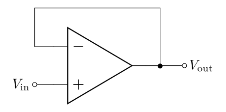
Figure 3 shows a voltage buffer circuit. First notice there is no power to the op-amp in the diagram; often you’ll find op-amp example circuits without power explicitly drawn in, but op-amps always need power (the power is implied - see Figure 6 for a pinout of the LF356 Op-amp that includes the power info).
2.6.1 Prelab Question
Start with \(V_\text{out}=A(V_+-V_-)\), and use the first two golden rules to show that \(G_0=1\) and that \(V_+=V_-\).
Hint: Start by plugging in \(V_+=V_\text{in}\) and \(V_-=V_\text{out}\) and solve for \(V_\text{out}/V_\text{in}\).
2.7 Non-Inverting Amplifier
Alongside the buffer, the non-inverting amplifier is one of the most used and simplest op-amp circuits; as the name implies, the non-inverting amplifier outputs a signal with greater amplitude than the input (without inverting it). It is very similar in design to the buffer, but with a resistor \(R_F\) in the feedback loop and a resistor \(R\) from the inverting input to ground. There are many ways you’ll see this diagram drawn as seen in Figure 4. Note that sometimes people draw the inverting input on top, and sometimes on bottom, but the feedback resistor always goes to the inverting input.
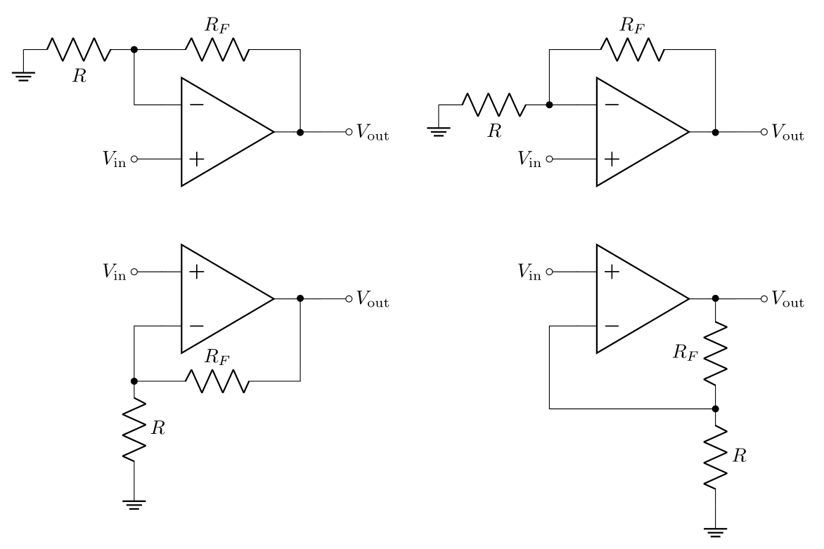
The two resistors form a voltage divider feedback network with a transfer function \(B\) (think of \(R_F\) as \(R_1\) and \(R\) as \(R_2\) in the voltage divider equation from lab 2):
\[B = \frac{R}{R_F+R}\]
2.7.1 Prelab Question
Use golden rules 2 and 3 to show that the DC gain, \(G_0\), of the non-inverting amplifier is
\[G_0 = \frac{1}{B} = 1 + \frac{R_F}{R}\]
Hint 1: First use the second golden rule and Kirchhoff’s current law to argue that the current flowing through \(R_F\) is the same as the current flowing through \(R\).
Hint 2: Use Kirkhoff’s voltage rule tracing from \(V_\text{out}\) to ground and from \(V_\text{in}\) to ground to make two equations. You can use these to find \(V_\text{out}/V_\text{in}\).
2.7.2 Prelab Question
Calculate \(G_0\) and the bandwidth, \(f_B\), for the non-inverting amplifier with \(R_F = 10\ \text{k}\Omega\) and \(R = 100\ \Omega\) (use the \(\text{GBW}\) you found in the datasheet to calculate \(f_B\)). Feel free to round \(G_0\) to a nice clean number ending in zero(s).
2.7.3 Prelab Question
Predict the amplitude of the output voltage, \(V_\text{out}\), for the non-inverting amp with \(R_F = 10\ k\Omega\) and \(R = 100\ \Omega\) when
\(V_\text{in} = 1\ \text{mV}\)
\(V_\text{in} = 1\ \text{V}\)
2.8 Input and Output Impedance of the Non-Inverting Amplifier
The non-inverting op-amp circuit has different input impedance, \(R_i'\), and output impedance, \(R_o'\), from the bare op-amp. You can find the derivation for how to find \(R_i'\) and \(R_o'\) in Horowitz and Hill 2nd ed. section 4.26 (copies can be found in the lab).
\[R_{i}' = R_{i}(1 + AB)\]
\[R_{o}' = \frac{R_{o}}{(1 + AB)}\]
where \(R_i\) and \(R_o\) are the input and output impedances of the bare op-amp (you already looked up \(R_i\) in the datasheet). These impedances will be improved from the values for the bare op-amp if \(A B\) is large (\(A\) is large, but \(B\le 1\)). With reasonable conditions, \(AB\) is still quite large. Notice then that in the non-inverting amplifier configuration, negative feedback causes the input impedance to increase (from an already large value) and the output impedance to decrease (from an already small value).
2.8.1 Prelab Question
The output impedance of the LF356 op-amp with no feedback is about \(40\ \Omega\) (and you already found \(R_i\) from the datasheet). Calculate \(R_i'\) and \(R_o'\) when \(R_F = 10\ k\Omega\) and \(R = 100\ \Omega\). Does it seem reasonable to assume the input impedance is infinitely large and the output impedance is \(0\)?
2.8.2 Prelab Question
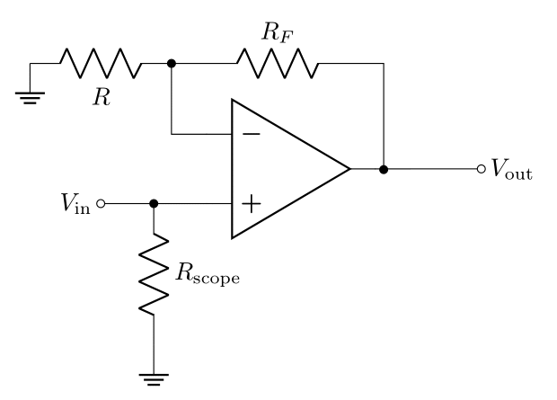
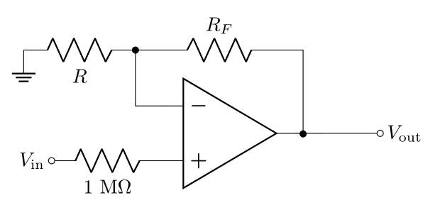
The oscilloscope has a finite measurement impedance \((1\text{ M}\Omega)\), so if you’re measuring \(V_\text{in}\), you are putting a resistor \(R_\text{scope}\) from the input to ground (see Figure 5). This will inevitably reduce the input impedance of the amplifier. In the case when \(R_F = 10\ k\Omega\) and \(R = 100\ \Omega\), what is the input impedance of the amplifier?
Hint: \(R_\text{scope}\) is in parallel with \(R_i'\).
2.8.3 Prelab Question
Maybe you already noticed that the buffer is a non-inverting amplifier with \(R_F=0\) and \(R=\infty\). We already know that it has a DC gain of 1, so \(B=1\). Calculate \(R_i'\) and \(R_o'\) for the buffer.
2.9 Powering the op-amp
Thus far, we’ve ignored the fact that the op-amp requires external power to operate, but the op-amp NEEDS external power to function. The recommended supply voltage to the LF356 is \(15\ \text{V}\) at the positive power pin \(V^+\) (aka \(+V_{cc}\) or \(+V_\text{supply}\)) and \(-15\ \text{V}\) at the negative power pin \(V^-\) (aka \(-V_{ee}\) or \(-V_\text{supply}\)).
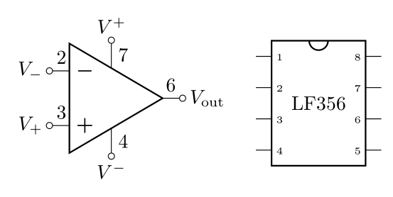
Here we can see the pin diagram for the LF356. Don’t confuse \(V_+\) and \(V^+\). The subscripts \(V_+\) and \(V_-\) refer to the non-inverting and inverting inputs and \(V^+\) and \(V^-\) refer to the power pins. Pins 2 and 3 are the inputs and 4 and 7 are for power.
We always want to apply decoupling capacitors to the the power: plugging one end as close to the power pin as possible and the other end into ground. Here’s a nice explanation why.
Definition 9: capacitive coupling - capacitive coupling is the process of sending a signal or energy through a capacitor (remember that the impedance of a capacitor is inversely proportional to the frequency). Capacitive coupling is a way of sending AC while blocking DC. Parasitic capacitance often leads to this happening by mistake.
Definition 10: decoupling capacitor - decoupling is coupling to ground. Decoupling capacitors charge up and provide a reservoir of energy that can be supplied to the circuit as the circuit’s current draw changes over time. Power supplies and transmission lines have inherent inductance which impedes changes in current, \(dI/dt\), so the decoupling capacitors compensate with the energy stored and provide the current necessary to maintain constant voltage.
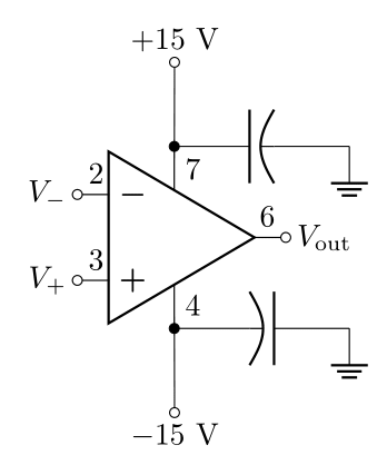
Each op-amp design has limits to how much voltage you can apply to the power pins (before something breaks), and typically there is a recommended voltage that is less than this limit (e.g. the LF356 can take up to \(\pm 22\ \text{V}\), but it recommends you apply \(\pm 15\ \text{V}\)). The voltage out is really coming from the power pins (the inputs, in a sense, just tell the op-amp how much of the power voltage to send to the output), so the maximum \(V_\text{out}\) depends on the supply voltage.
2.9.1 Prelab Question
Check the datasheet for the maximum output voltage when the LF356 is powered with \(\pm 15\ \text{V}\). This is usually referred to as the output voltage swing.
2.9.2 Prelab Question
Look back at your calculations in prelab question 2.7.3; when supplying the LF356 with \(\pm 15\ \text{V}\), what do you expect happens when the predicted \(V_\text{out}\) is greater than the output voltage swing?
2.9.3 Prelab Question
There are many choices of op-amps in LTSpice. You can find them in the component’s menu (P is the shortcut). In the search bar, type “op” to open the op-amp folder. Selecting an op-amp will reveal a short description of each. In most cases, it doesn’t matter which you choose for your simulations, and unfortunately, the LF356, isn’t built in to the program. The OP07 (which should pop up first in the search) acts fairly ideally; however, for this activity, we will choose the OP113 since it more accurately responds to a non-ideal voltage supply.
Create two voltage supplies off to the side and wire them together just like the figure below. Making them both \(+15\text{ V}\) but grounding the middle will get both plus and minus voltages (just like you do with your real power supply in the lab).
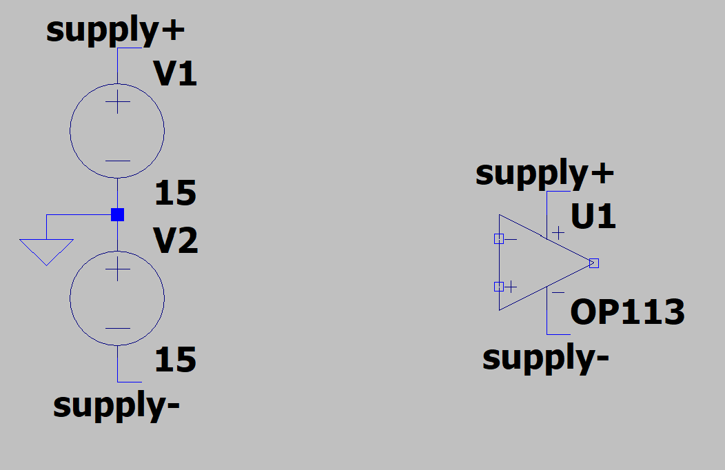
Use the “Label Net” tool (it is labeled as “net” in the toolbar) to label the positive end of the power supply “supply+” and the negative end “supply-”, then you can label the two power pins of the op-amp the same (as seen in the figure above). Net labels are a way of making connections between things without having to clutter your diagram with wires. Note: the ground symbol is a net label as well.
- In the figure, the text is made to be horizontal by adding a little L-shaped tail of wire to the node. This is a stylistic choice.
Make a voltage buffer circuit (see below) with a input voltage with a \(1\text{ V}\) amplitude and \(1\text{ kHz}\). Set up the simulation such that about 5 oscillations will be visible (make the stop time 5 times the period).
Measure the input and output voltage of the buffer. Calculate the transfer function. It should be 1.
Measure the current into the op-amp at “supply+” and at “supply-”. The voltage is obviously a DC 15 (or -15) volts, but is the current DC?
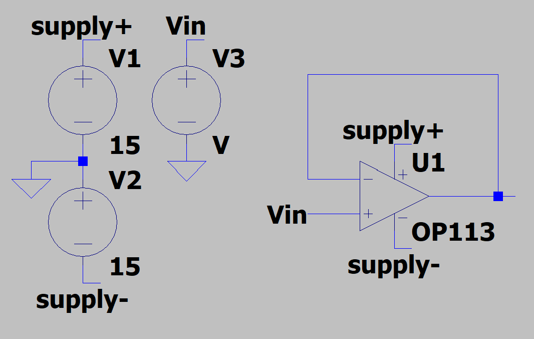
- The simulation does not need decoupling capacitors for powering the op-amp because the voltage supplies in the simulation are ideal. Next we will simulate the effect of a non-ideal power supply. To do this, add inductors in series with the outputs of the power supply. The exact value isn’t very important, but \(1\text{ mH}\) is a fine choice.

Re-run the simulation and record the results of \(V_\text{out}\). Measure and record the voltage at the power pins of the op-amp, and describe why the voltage is no longer DC.
This can be resolved by adding decoupling capacitors as seen in the figure below.
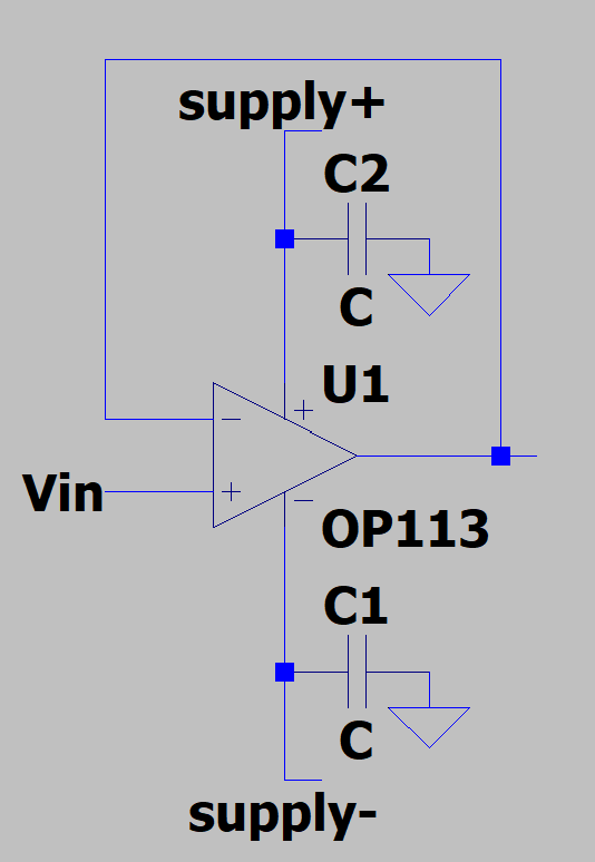
- A good choice for capacitance here is \(1\text{ uF}\) (microfarad). Re-run the simulation and report the results.
2.10 Lab activities
2.10.1 Prelab Question
Please review the lab activities so that you’re better prepared when you arrive to your lab section.
3 Op-amp TLDR
This section summarizes information covered in the prelab (you may find this useful for a quick reference in the future).
The op-amp is a differential amplifier that outputs an amplified difference between the inputs:
\[V_\text{out}=A(V_+-V_-)\]
Feeding the output back into the inverting input drives the system into a very stable state which no longer depends on many of the details or imperfections of the internal workings. Closed-loop refers to the state of an op-amp with feedback, and open-loop refers to the state of an op-amp with no feedback.
3.1 Golden Rules
The golden rules are approximations that make op-amp analysis relatively simple and straight forward.
- The open-loop gain is infinitely large: \[A\rightarrow\infty\]
- The input impedance is infinitely large, so no current flows in or out of the inputs: \[I_+=I_-=0\]
- When negative feedback is applied, the output drives the inverting input to be the same voltage as the non-inverting input: \[V_+=V_-\]
3.2 Definitions
Here are all the terms we defined in the prelab:
Open-loop gain, \(A\) - the gain of the op-amp when there is no feedback.
Open-loop DC gain, \(A_\text{VOL}\) - the open-loop gain at low frequencies before the frequency dependence starts to take over and the open-loop gain starts to decrease. This is cited in any op-amp datasheet (sometimes as \(A_\text{OL}\) or \(A_\text{VO}\)).
Open-loop 3 dB point, \(f_0\) - the frequency that the open-loop gain falls -3 dB from \(A_\text{VOL}\). Beyond this frequency, \(A\) typically continues to fall with a constant dB per log-scale (quoted in dB/octave (log2) or dB/decade (log10)). This value is usually not quoted in datasheets. It can be calculated from other values, and people often aren’t concerned with the value of \(f_0\).
Closed-loop gain, \(G\) - when a fraction of the output is fed back into the inverting input \(V_-\), the op-amp’s gain is greatly reduced from \(A\) to some value \(G\). Just like the open-loop gain, this value is frequency dependent and starts to fall from \(G_0\) near the 3 dB point, \(f_B\).
Closed-loop DC gain, \(G_0\) - the closed-loop gain at frequencies well below the 3 dB point. Except in active filter design, the point of an op-amp is to operate at a frequency such that \(G(f)=G_0\), so almost always, the closed-loop DC gain is referred to simply as THE gain.
3 dB point, \(f_B\) - the frequency where \(G\) drops -3 dB from \(G_0\). This is also often referred to as the bandwidth or operating bandwidth, as typical operation should be done below this frequency.
Gain bandwidth product, \(\text{GBW}\) - the product of the DC gain and the 3 dB point is a constant value. This should be cited in datasheets as it’s a foundational property of each op-amp’s internal design. Just like resistor values, however, the precise \(\text{GBW}\) varies from op-amp to op-amp of the same name.
Unity gain frequency, \(f_T\) - the 3 dB point when the gain is 1 (unity). Since this is mathematically equivalent to the \(\text{GBW}\), these terms are often used interchangeably.
Capacitive coupling - capacitive coupling is the process of sending a signal or energy through a capacitor (remember that the impedance of a capacitor is inversely proportional to the frequency). Capacitive coupling is a way of sending AC while blocking DC. Parasitic capacitance often leads to this happening by mistake.
Decoupling capacitor - decoupling is coupling to ground. Decoupling capacitors charge up and provide a reservoir of energy that can be supplied to the circuit as the circuit’s current draw changes over time. Power supplies and transmission lines have inherent inductance which impedes changes in current, \(dI/dt\), so the decoupling capacitors compensate with the energy stored and provide the current necessary to maintain constant voltage.
4 Useful Readings
You can find more on op-amps from these recommended sources:
Steck Sections 7.1, 7.2, 7.3.1, 7.3.3
Fischer-Cripps Sections 12.2 - 12.15
Horowitz and Hill 2nd Ed., 4.01. 4.02, 4.03, 4.05, 4.06
Horowitz and Hill 3rd Ed., 4.1, 4.2.2, 4.2.3
Open Circuits - 40, 52, 76
5 IC Tips
In this lab, we will use ICs (integrated circuits) for the first time. ICs come in many forms; we will be using DIP chips because these are designed for using in breadboards. DIP is a description of the packaging they come in: resembling little bugs with legs running down each side. These basic tips should always be followed when working with ICs. Read through them all (likely more than once) before you begin using any IC chips. You should refer back to this section in future labs to remind yourself of these useful tips.
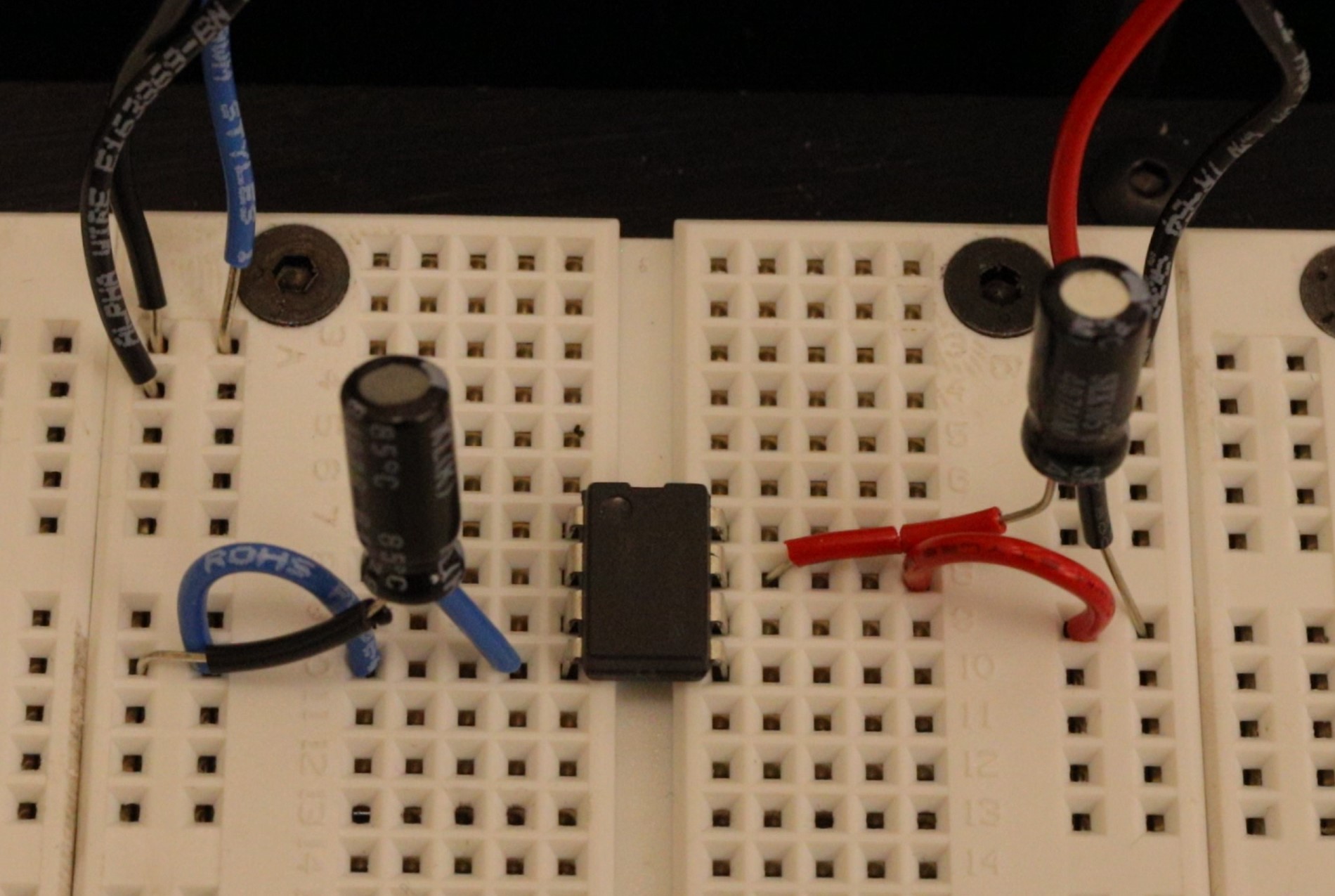
- Always unplug the power supply from your circuit while you’re wiring it.
- Chips sit across the groove on the breadboard (see Figure
12). Any other placement will
cause legs to short together.
- Before inserting a chip, ensure the pins are straight (using a needle-nose pliers or something similar).
- After insertion, check visually that no pin is broken or bent under the chip.
- To remove the chip, use the dedicated IC pliers (found in the tool trays at your lab station). Removing ICs by hand often results in bent legs and/or a leg puncturing your finger.
- Use the long columns on your breadboard for your power and ground voltages (with power and ground next to each other) to take advantage of the parasitic decoupling capacitance of the long line.
- Color code your wires. We recommend:
0V (ground) Black
+15V Red
-15V Blue
Use other colors for any other connections which aren’t to \(\pm\) power or ground
- Connect capacitors between the power pin(s) of the IC (as close to the pin as possible as in Figure 12) to ground. These are called decoupling or bypass capacitors and are critical for maintaining constant voltage at the pin as the current needs change. Use nice, big polarized (electrolytic) capacitors (\(>1\ \mu\text{F}\)) so that they’re able to collect enough charge to deliver the necessary current when needed.
- Measure all your passive elements (resistors, capacitors, inductors, diodes) before putting them in the circuits; trying to measure while they are plugged into the breadboard can lead to mistakes.
- Always have a diagram of your circuit with pin numbers labeled (like the left side of Figure 6).
- Make sure any polarized (electrolytic) capacitors are oriented such that the higher voltage is applied to the correct lead of the capacitor. Remember: ground is a HIGHER voltage than \(-15\ \text{V}\). Getting this backward will cause the capacitor to explode: this is loud, smelly, and a bit embarrassing.
- Wires that your signal go through should be kept short and compact. This minimizes the parasitic inductance and capacitance and will better preserve the signal. Don’t put your signals into the long columns running down the breadboard.
- Don’t make any connections that cross over the top of the
IC (like the feedback connection for an op-amp); instead, go
around the IC.
- This makes it so you can pull out the IC without disturbing the rest of the circuit.
- This helps ensure magnetic fields generated by the current in the wire don’t interact with the inner workings of the IC.
- Compare your physical circuit to the diagram before connecting the power supply (especially polarized capacitor orientations).
6 Lab Activities
6.1 Building an op-amp test circuit
Before you build any useful op-amp circuits, let’s build a simple means to test if an op-amp chip is functioning.
When building circuits, it’s a good idea to test components before putting them all together in a complex circuit. This can save you a lot of headaches by avoiding needing to debug your circuit because you have a burnt out or broken IC.
You should consider leaving the “bones” of this test circuit somewhere on your breadboard so that you can quickly pop in an LF356 chip to test it (keep it compact and leave plenty of space on your breadboard for future work).
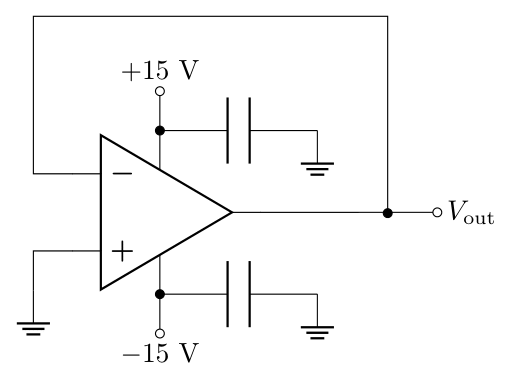
The test circuit resembles the buffer, but with \(V_\text{in}=0\).
Predict the voltage at pins 2, 3, 4, 6, and 7 of the test circuit.
Build the test circuit as shown above (review the IC tips).
Measure and record the voltages at pins 2, 3, 4, 6, and 7. Do they match your predictions? If not, revise your predictions or decide that the op-amp is broken. Check in with an instructor if you are unsure.
Commonly, when a chip isn’t working, it will output roughly \(15\ \text{V}\) or \(-15\ \text{V}\) at pin 6 regardless of the configuration. If you find you have a bad chip, throw it in the trash and grab another (In case you are wondering, the LF356 costs less than $1). If you’re not sure, grab an instructor and have them take a look with you.
6.2 Voltage Buffer
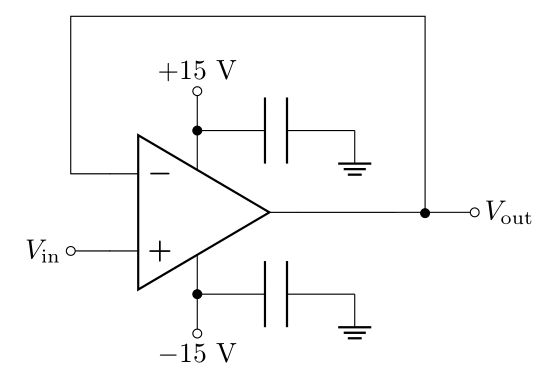
A voltage buffer is an incredibly useful circuit which isolates an input voltage from the driving output, allowing you to drive loads from the function generator without drawing any current from it (the current will be sourced from the power supply instead). Two weeks ago, you tried to power a speaker directly with the function generator and found that too much of the voltage divides over the output impedance for it to be useful. The follower will allow you to overcome this limitation of the function generator.
The voltage buffer is essentially a non-inverting amplifier with a gain of 1, so it is often also referred to as a follower (since the output “follows” the input). The buffer gets its name because no current flows through the input and therefore the voltage at the output is, in a sense, isolated from the voltage at the input (even though they’re the same value). This can help you avoid unintended issues with voltage dividers: such as the one you encountered above with the function generator, as well as having measurement impedances or loads in parallel with a voltage divider changing how much current goes through \(R_2\) (you also encountered this in Lab 2).
You will use the buffer to take the output of the function generator (with a \(50\ \Omega\) output impedance) and reproduce (i.e. follow) the same voltage with a very small output impedance (we calculated this in prelab question 2.8.3)
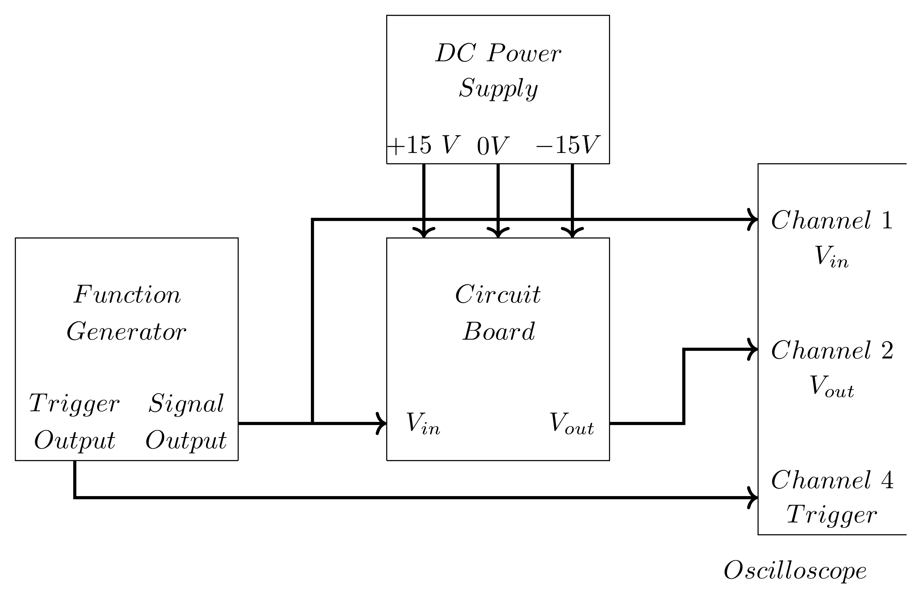
Build the voltage follower using the function generator as \(V_\text{in}\), set to a \(400\text{ mV}_\text{pp}\) sine wave at \(432\text{ Hz}\) (like we did in Lab 2). Figure 15 shows a schematic of the full set up using Channel 1 to measure \(V_\text{in}\), Channel 2 to measure \(V_\text{out}\), and Channel 4 to trigger on the Sync output. You should use an oscilloscope probe for this measurement (and probably all oscilloscope measurements for the rest of your electronics career, but certainly for this course).
Confirm the gain is \(1\). If the gain is \(10\) or \(0.1\), this is likely due to a setting on the oscilloscope (ask for help if you’re lost).
Connect the speaker from \(V_\text{out}\) to ground. Does \(V_\text{in}\) or \(V_\text{out}\) change?
Why or why not? Is this expected?
Increase the amplitude on the function generator to \(500\text{ mV}_\text{pp}\). Describe what happens to \(V_\text{out}\).
Play with the amplitude to see if this behavior is consistent. Record what you’re doing and what you’re seeing along the way.
Why is this happening? Is this consistent with what you found in the prelab? This is a good place to check in with an instructor to confirm your thinking or clear up any confusion.
Unplug your speaker!
There are op-amps which have higher max output currents. These are sometimes referred to as “power op-amps” and are in form factors designed to attach to heat sinks (since high currents produce a lot of heat).
6.3 Non-Inverting Amplifier
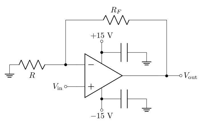
Grab a \(10\text{ k}\Omega\) and a \(100\ \Omega\) resistor and measure their resistances.
Change the negative feedback loop in your circuit to the one shown in Figure 16, with \(R_F = 10\text{ k}\Omega\) and \(R = 100\ \Omega\) (or build a new one elsewhere on your breadboard).
You calculated \(G_0\) and \(f_B\) for this circuit in the prelab, recalculate these values for the measured values of \(R\) and \(R_F\).
What’s a reasonable amplitude to set for \(V_\text{in}\)? Why? Set the function generator to this.
What’s a reasonable frequency to set so that \(G(f)=G_0\)? Why? Set the function generator to this. (consider the gain bandwidth product and/or your Bode plots).
Measure the amplitude of \(V_\text{in}\) and \(V_\text{out}\) and then calculate the gain. How does this compare to your prediction?
6.3.1 Frequency limitations of the amplifier
Set the frequency to the calculated 3 dB frequency and measure the gain. Is this -3 dB less than the previous gain? If not, change the frequency until you find the frequency at which the gain is -3 dB less than \(G_0\). What is the measured 3 dB frequency?
Use the previous result to calculate the gain bandwidth product. How does this compare to the datasheet?
Record measurements of the gain and frequency at a few points near the 3 dB frequency, a point roughly an order of magnitude above and below, and a point roughly two orders of magnitude above and below.
Make a new Bode plot based on your updated Gain Bandwidth Product along with these data points. Do your measurements agree with the model?
6.3.2 Output voltage limitations of the amplifier
Return the frequency to a “low” frequency when \(G=G_0\). Increase the voltage until you see the signal saturate (this is also referred to as clipping). Measure the output saturation levels, \(+V_\text{sat}\) and \(–V_\text{sat}\)? Record how you determined \(V_\text{sat}\). Can \(V_\text{out}\) produce voltages that span the voltages applied (\(-15\text{ V}\) to \(+15\text{ V}\)) to the op-amp?
The model of the op-amp you have been working with does not include saturation effects. To make sure you are working within the range where your model is most accurate, make sure the output amplitude is below half the saturated value. Change the amplitude of the input so that the output is within this range.
6.3.3 Input impedance of the amplifier
- Unplug \(V_\text{in}\) from the oscilloscope so that the input impedance is the full \(R_o'\) calculated in the prelab. Predict what happens if you add a \(1\text{ M}\Omega\) resistor in series with \(V_\text{in}\). Hint: consider the voltage drop across the resistor, and consider how adding this resistor changes in the input impedance. Do your measurements agree with your predictions?
6.3.4 Output impedance of the amplifier
Consider driving a load with resistance \(R_L\) with the output of your amplifier and the effects of the output impedance \(R_o'\). Write a relation between the amount of \(V_\text{out}\) makes it across \(R_L\) as a function of \(R_L\).
Predict the maximum \(V_\text{in}\) you can use to avoid hitting the maximum output current when \(R_L\) is equal to the resistance you measured for the speaker (don’t forget to consider the output impedance). Set the input to be just less than this, and set the frequency back to \((432\ \text{Hz})\).
Record \(V_\text{out}\) and confirm the gain is what you expect.
Plug in the speaker. Record \(V_\text{out}\) again. Did \(V_\text{out}\) change? By how much?
We can refer to the output when a load is attached as \(V_\text{out}^{(L)}\) and \(V_\text{out}\) as the output when no load attached. Use the ratio of \(\frac{V_\text{out}^{(L)}}{V_\text{out}}\) to calculate the output impedance of the non-inverting amplifier.
If you wanted all of the output to drop across the load instead of having a significant portion drop across the output impedance, what changes could you make to the circuit, or what elements could you add to achieve the same gain but with lower output impedance?